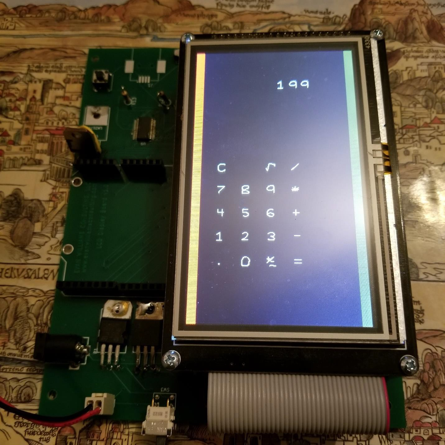
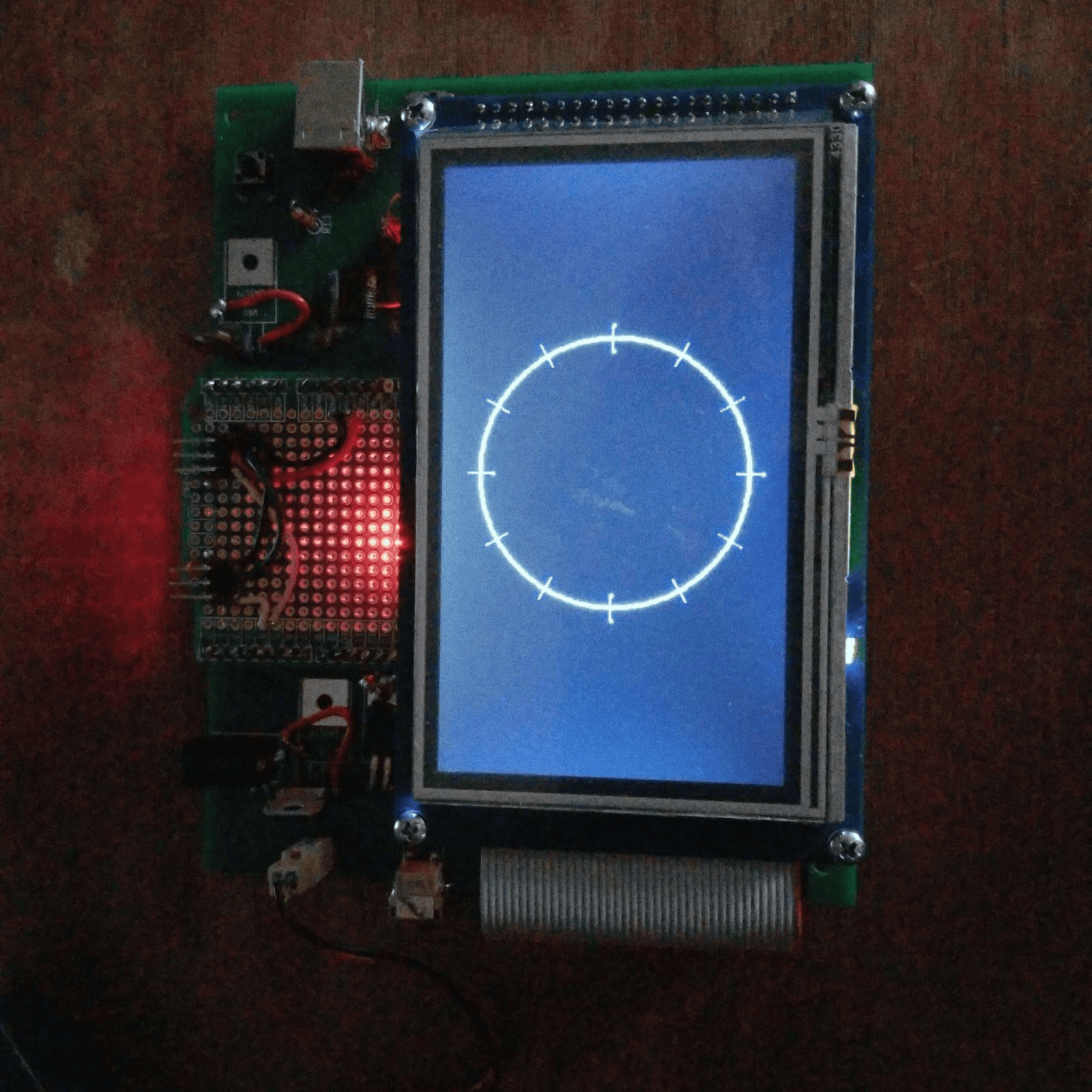
What is the LCD Display Board?
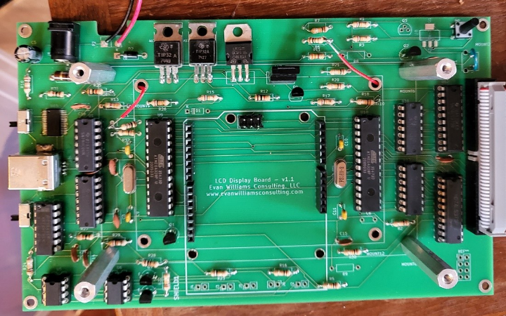
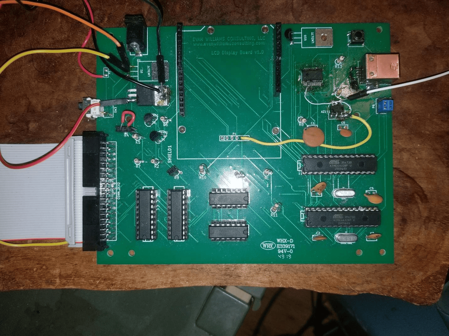
The LCD Display Board is an interface board for a standard LCD Screen that interfaces with an old-style 8080 / 6800 interface. It uses two Atmel 328P Microcontrollers (also found in the Arduino UNO). One Microcontroller is used to operate the LCD, the other is used for accessories including the pinouts required for an Arduino-style shield (daughter board).
II. Features and Benefits
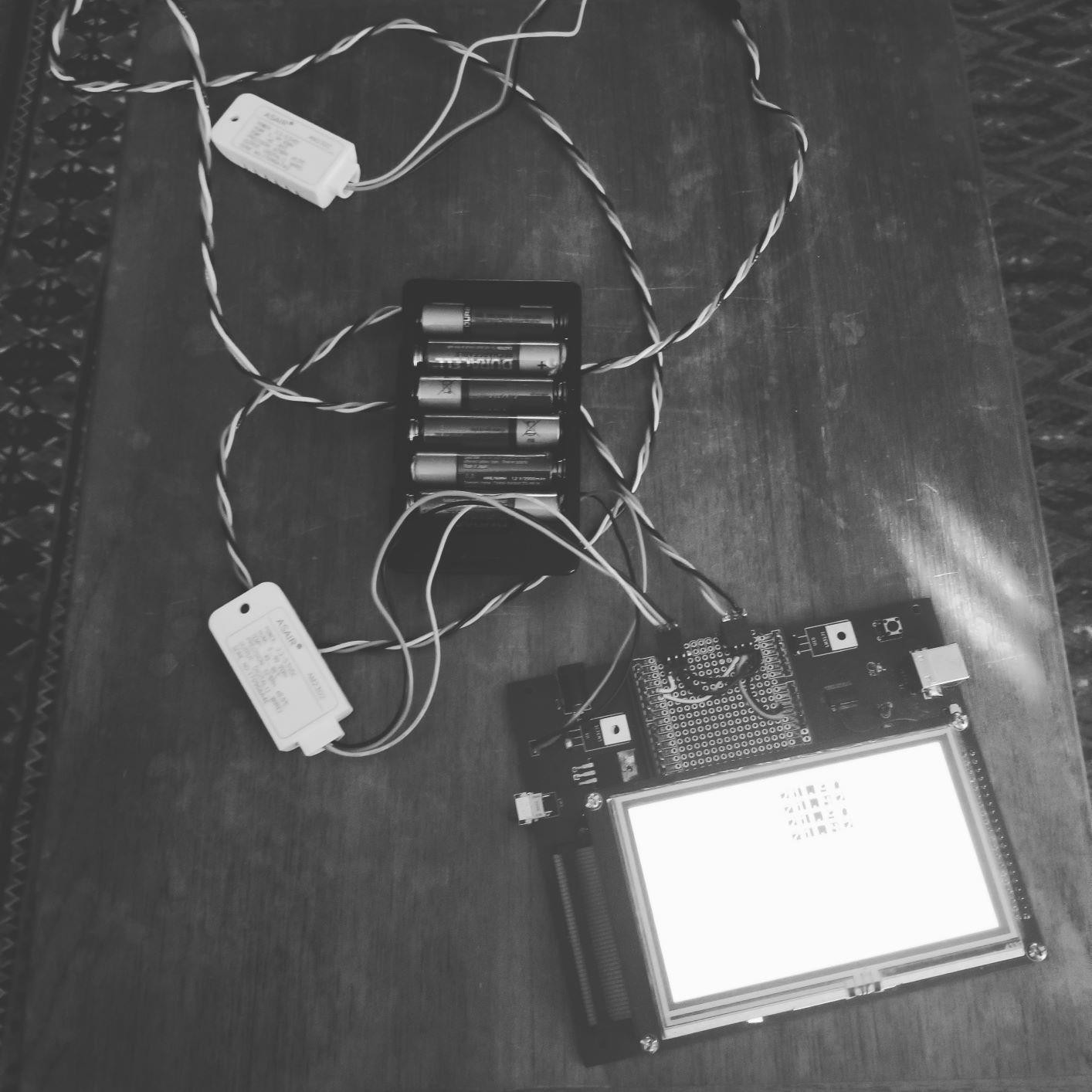
a. Battery Powered – 6V – 12V Input or 6 AA cells (rechargeable) approximately 8V
b. 12 V DC Input for recharging the battery.
c. Standard Arduino UNO – friendly programming. Sketches built on a normal UNO will continue to function -- * with a LCD screen *
d. Why use this board instead of a standard LCD Screen built for Arduino? There are several reasons:
i. Most screens use most available digital pins of the UNO requiring an upgrade to an Arduino Mega or a more expensive display (such as Smart GPU) with an I2C or Serial backpack.
ii. The second MPU allows display processing to go on without disturbing the normal operation of the sketch.
iii. The board has additional features such as battery charging and Bluetooth.
iv. The board can programmed with a standard IDE such as is used for the Arduino UNO.
v. Board has power-off switch
vi. Current board is retro with DIP sockets especially for the MPU.
III. Upgrade Path
a. New Display
b. More Power (ARM on board)
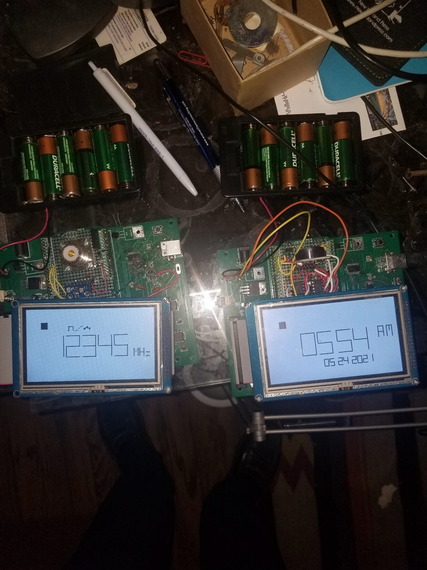
c. Real-Time Clock
d. Better Bluetooth
e. Frequency Generator
f. Sound
IV. New Edition of Current Module
a. This display interface is common even though It is an older design. Why change It right now (remain retro).
b. SMT parts could be used. The Atmel 328PB replaces the Atmel 328p. There would be circuit changes required and the new chip has not been prototyped in this circuit.
c. One Atmel 328P (for the graphics interface) could be upgraded to an Arduino Mega style chipset (Atmel 2560) or the lesser-known Atmel 1284. The Atmel 1284 comes in a 40 pin DIP package if the “retro” style is important. The Atmel 1284 has 128K of memory on board for programming – more than the current and limited 32K on the Atmel 328P. The Atmel 1284 has not been tested and it is not clear if it can be programmed using the standard Arduino – style IDE. The Atmel 2560, used in the Arduino Mega, does not have these limitations but has many more output pins than needed to run the display.
V. Upgrade
a. Possible Improvements
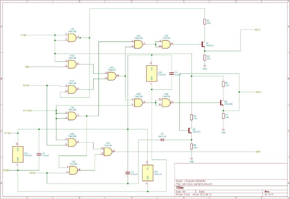
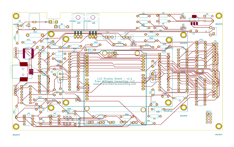
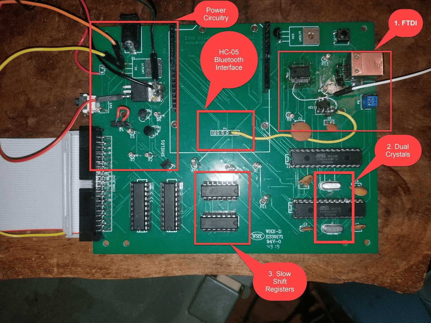
i. The switch on the right (.1” Jumpers in the picture) could be wired so that when no cable is plugged into the USB Type A jack, the serial would fail over to connect MPU1 to MPU2. This would be a good thing because many standard sketch libraries come with a Serial Interface ready to go. The board currently uses I2C for inter-MPU communication. The DTS line from the FT232RL chip can determine whether the cable is present. This circuitry has not been tested however the above board has been wired with the jumpers to allow me to do so.
ii. The two MPUs each have a separate external crystal. This could be replaced with one crystal and one external clock (Preferable?). However the MPUs must have a fuse burned during programming to permit an external clock to be used. There is a known circuit design using one crystal for both MPUs using the internal clock circuitry with identical circuit path lengths however this does not seem like a good idea.
iii. The shift registers slow the LCD screen down by x16. Upgrading the second Atmel MPU to a larger chip and eliminating the shift registers would solve this problem.
b. Wiring Errors
i. Power (5V) to pin 4 of FTDI chip (FT232RL) (white wire front side).
ii. 3.3V regulator was not powered with 5V (yellow wire front side).
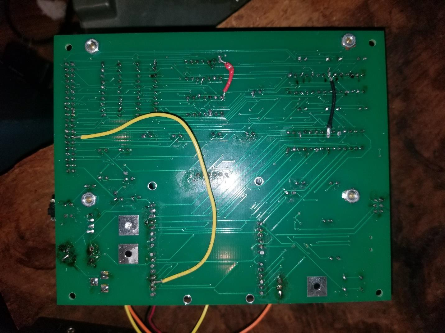
iii. Because there are not enough pins on the Atmel 328P MPU I wired the interrupt request line from the touch screen to the second MPU2. That is cumbersome because the MPU2 must currently used I2C to tell MPU1 that a touch has occurred. (yellow wire rear side).
iv. Power to one of the shift registers was not provided (red wire rear side).
v. MPU1 was not provided with ground (black wire rear side)
c. Circuit Errors
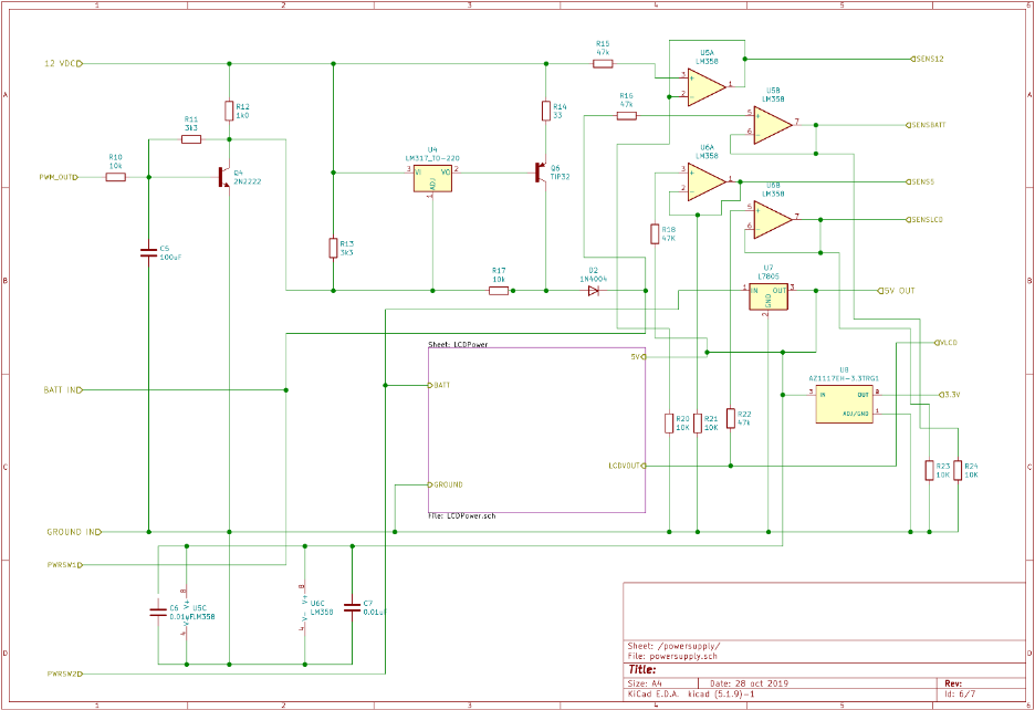
i. I have a new battery charging circuit that operates properly. It uses a LM317 and a TIP31C transistor.
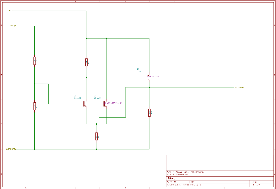
ii. Display power circuitry is good except that the output transistor was replaced with a 2N2222.
iii. Proper spacing of battery terminals on PCB Board.
iv. Since the DC Input Jack has a switch on board do we need to use a fancy DPDT power off switch?
v. Missing ISCP header for Arduino shield
vi. Double check all pins on Arduino shield, especially power pins
vii. Missing extra pins for Arduino shield – are they needed?
viii. Should Bluetooth and Real-Time Clock circuit be onboarded?
d. Form Factor
i. Size of 7” screen
ii. Bluetooth Module should be on edge of board
iii. Mounting holes for 7”, 5” and 3” screens.